
Laser Cutter Build v1 (2018)
//IF YOU’RE INTERESTED IN BUILDING YOUR OWN CHECK OUT MY ‘VERSION 2’ LASER CUTTER BUILD SERIES
DESIGNING & BUILDING A CUSTOM CO2 LASER CUTTER. 2018.
I optimized the layout of the gantry and components to maximize the effective bed area while minimizing the overall footprint so it could still be shifted and transported with relative ease.
Designed in Rhino, my CAD file is available for download here
Written Build Log below:

I thought it would be valuable to share an overview of my experience and explain my reasoning and methodologies, so even if you’re not specifically interested in building a complete laser cutter from scratch, you’ll hopefully be able to take something away from this.
I started by modelling the assemblies in CAD - I used Rhino because that’s what I was fastest with at the time, but if I was doing it again I’d use Fusion 360 for it’s parametric features. The design considerations were mainly motivated by 2 things - size and price. I wanted to make the cutting bed area as large as possible for the overall footprint of the machine, and that footprint could be no wider than a door frame, since a single door was the only way in or out of my shed. This should correspond with optimizing the size of components to a common metric, I’m using aluminium slotted profile for the build, which are typically sold in 1 metre length so having components that were say 510mm would be more wasteful than say 490mm, so that was something to be aware of. So after I had gone through a few different iterations, I was comfortable with the design. So pulled the trigger and started ordering parts.

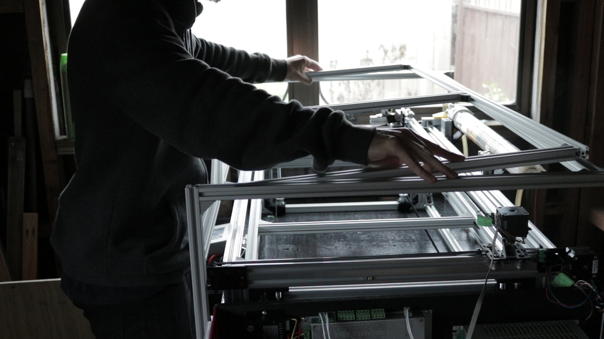
The first stage was the creating the x and y gantry from 4020 aluminium v slot rail. I’m using my regular wood blade to cut the aluminium, but I have it clamped to the work surface and I’m feeding the blade through quite slowly. For getting accurate cuts across multiple parts I tape them together a make a single cut.

With the aluminium cut I can start to see my gantry area IRL for the first time, right now it’s 1 meter by half a meter and but once all the hardware is on and assembled I’d like to have a 800 by 400mm effective cutting area.

Because this is my first time using the v-slot rail system in a project. I spent a bit of time figuring out the best method of assembly, it’s all quite intuitive but i did find pressing the bearings in flush required a bit of finessing.

What’s awesome about using slotted aluminum profiles is how quickly parts can go together and being able to get a rolling gantry within an hour or so really satisfying.

With the gantry plates on I started assembling the belt hardware, I actually ended up having to grind a small groove in all for corners of the v slot, so the belt could run smoothly. I didn’t notice that collision in the 3d model because I had the belt laying across the top on the aluminum, whereas in reality it does like to sit lower into the slot.

This is the x axis gantry plate, which I made from two layers of cast acrylic. I had to custom make this because I designed the plate to span the 40mm long side of the rail rather than the standard 20mm short side. I did it like that to minimise racking forces, but it obviously a bit more of a hassle than just buying a standard component.

For holding the laser mirrors to the gantries I used cast acrylic again, to make them double thickness i joined the two layers with acrylic welding cement which chemically bonds the parts together.

I’m using 3d printed parts for many of the components and here I’m assembling the laser tube holder. I 3d printed initial prototype parts in PLA before reprinting them later in ABS for better long term performance.

With the x and y axis locked in I could assemble the z axis. Determining the height of the z axis was more of a best guess type thing. I didn’t want to undersell myself by making it so shallow I was restricted to thin sheet goods, but going too deep would be wasteful for construction and space so I opted for a safe middle ground of 200mm.

From here on in the build I’m using t-slot aluminium profile rather than the v-slot. The v-slot is specifically designed for having the moving gantry components attached to it and is a little bit more expensive and harder to get. So for just framing applications t-slot’s slightly more economical. If you’re new to slotted aluminium profiles, generally the easiest way to assemble parts is to ‘pre load’ brackets and other hardware, slide them into the slots and then go through and tighten it down once you’ve got everything aligned.
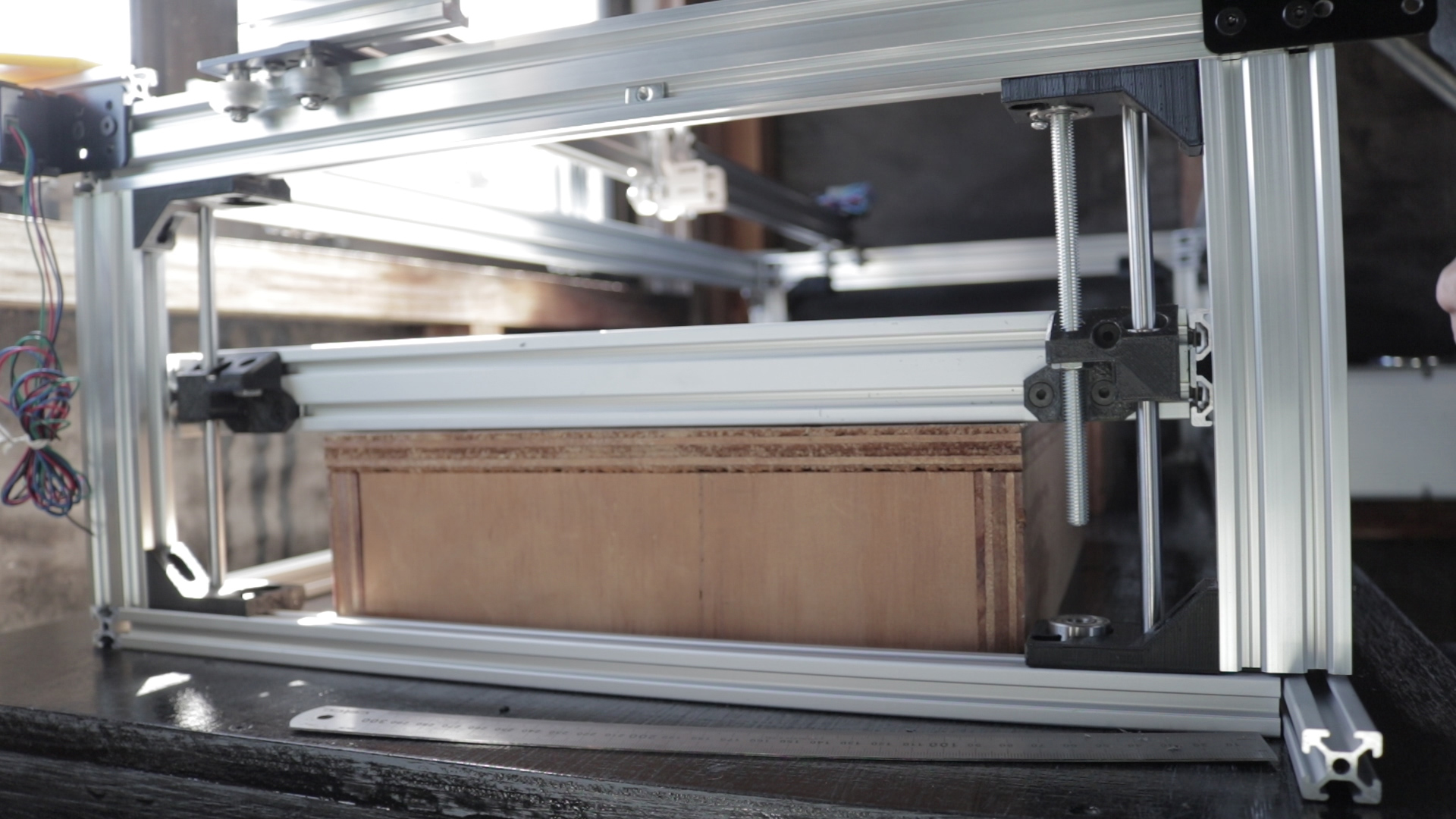
I designed the z axis to raise and lower via 8mm threaded rods in each corner with 8mm smooth rods and linear bearing to guide them. Movement is from a 10mm wide gt2 closed belt running around pulleys at the base of the threaded rods. and will just be hand operated for simplicity at this stage. The cutting bed frame uses 4020 t-slot for extra rigidity across the length, and 2020 bracing on the inside because I’m trying to keep costs down With the z axis fitted and the bed moving it was time to tackle the electronics.

I had originally planned to install the electronics in a drawer in the back of the base where they’d be hidden away and not take up space. I quickly realised when I mocked this up that accessibility was going to be a nightmare so I opted instead to make an external box where I could easily get to the wiring.

I’m using a AWC608 COMMERCIAL DSP controller system, which comes with it’s own CAM software. This is maybe a more expensive option than going down the opensource route but everything is basically plug and play and it comes with a really solid interface. With everything set out then it was just a matter of methodically wiring up each part.

Once everything was kinda connected I wanted to get the axis driving around. so I fitted on the 6mm wide gt2 timing belts - which are a little narrow in this application- I also had to go round a filed off some of the corners of the aluminium profile as they were still snagging the belt slightly.

Fitting the mechanical limit switches was a straightforward process of finding a good solid contacting position and then drilling, tapping and bolting them into place.

With that done and a bit of calibration to get the axis stepper motors running correctly I could finally test out the gantry CNC motion.

With everything now moving it was time to take the next major step - installing the actual laser. I placed the tube into position and fixed the mirrors onto the axis.

My laser uses a water cooling system, so I topped that up and began the slow process of aligning the laser beam.

This process is to make the laser beam run perfectly inline across the length and width of the x and y axis as the beam is bounced through 3 mirrors. This is done by adjusting the height, position and angle of tube, mirrors and nozzle sequentially until you can get the laser beam landing consistently.

Now that the motion was working and the laser was firing I could start in on enclosing it all up. The first thing I used the laser for was to cut a face plate so I could tidy up the electronics. For monitoring I’m using both a digital and analog ammeters. because the analog metre doesn’t jump around as quickly and so gives clearer overall readings.
For the outer enclosure I was originally just going to bang something out using wood I had lying around. However after mocking that up I realised how bad it would look and how much extra time it would take - so I stayed with the t-slot profiles.

One of my larger design choices was to have an entirely separate outer enclosure over the xyz gantry. In almost all the designs I researched the gantry axis were part of or connected to the outerframe of the machine itself. I wanted to have my gantry self contained for the reason that it would be easier to keep square and rigid and if anything were to impact the laser machine, it would only hit the outer enclosure and not affect to inner gantry at all. It also meant that I didn’t need to bog myself down on building the outer enclosure to sub mm tolerances which saved on material cost and time.

I wanted to make everything as accessible as possible, so for the front panel I went with a sliding door layout with a clear panel in the middle. This allowed me to easily get into the bottom of the machine, be able to lift the panels completely out if I wanted to fit oversize materials in, and also give me visibility so I could see the underside of the material being cut. I didn’t go with a hinged door because space was too tight and when open, it would always kinda be in the way.

Well I think that pretty much covers it, honestly I could talk for hours on all the details of parts and components, but I think the easiest thing is, if you have any questions I’ll do my best to answer them. If you download my rhino CAD file just use it purely for general reference, as I didn’t stick to it 100%. Also congratulations on reading this far.